BMA Mobile - Operating Instructions
1. Product overview
Product identification
- Product name: BERNARD Mobility Analyser Mobile (BMA Mobile)
- Model: BMA Mobile with 2.7 mm focal length
- Hardware revision: v3
The complete BMA Mobile system consists of two articles:
| Article number | Article | Description |
|---|---|---|
| 100506 | BMA | BMA detector, hardware revision v3, with 2.7 mm focal length |
| 100507 | Battery/mast set | Battery box with 100 Ah battery, carbon telescopic mast, and charger |
Short description
The BMA Mobile is a battery-powered system for temporary traffic surveys. It combines the BMA detector (article 100506) with the battery/mast set for BMA Mobile (article 100507). Image data is evaluated directly on the detector. Detected objects can trigger events that are transmitted as JSON via MQTT. Central management is handled through the Control Center.
Target group and qualification
Installation and commissioning may only be carried out by trained specialist personnel. Operation is only permitted for instructed users.
Operator responsibility
The operator is responsible for integrating the BMA into a higher-level system and for evaluating the detection data and events provided by the device.
Intended use
The BMA Mobile may be used for temporary traffic surveys, for example for:
- traffic counting (cross-section)
- turning movement counting
- parking surveys
Improper use
The BMA is not intended for:
- safety-critical functions where incorrect or missing detection could lead to injury or property damage
- legally binding evidence collection or surveillance in the context of public-authority tasks
- operation outside the specified operating conditions or with an obstructed / unsuitable field of view
2. Safety
Signal words and symbols
DANGER
Hazardous situation which, if not avoided, will result in death or serious injury.
WARNING
Hazardous situation which, if not avoided, could result in death or serious injury.
CAUTION
Hazardous situation which, if not avoided, could result in minor or moderate injury.
NOTICE
Possible property damage or important additional information.
General safety
- Installation only by qualified personnel.
- Secure ladders or lifting platforms when working at height.
- Secure the work area against falling parts during installation.
Electrical safety
- Disconnect the power supply before installation and wiring; work on electrical connections must only be performed in a de-energized state.
- Only establish the power supply in accordance with the product specification.
- Check cables and connectors for damage before commissioning.
- Take the BMA out of operation and contact support if cables or connectors are damaged.
Mechanical safety
- Attach the mobile system only to suitable, load-bearing fixed infrastructure.
- Ensure that detector, telescopic mast, mounting bracket, tensioning straps, and battery box are firmly attached.
- Tighten all fastening elements properly.
- Secure the battery box, tensioning straps, and mast lock against unauthorized removal.
- Perform a visual inspection after installation (secure fit, no loose parts).
IP protection and environmental conditions
- To maintain the IP protection rating, point cable connections downward and fully lock all plug connections.
- Route cables properly and ensure strain relief.
- Operate the detector only within the specified operating conditions (see Technical data).
- Do not open the device (no serviceable parts inside; opening voids the warranty).
3. Technical data
| General | |
|---|---|
| Function | Temporary detection of moving and stationary traffic |
| Typical applications | |
| Model | BMA Mobile with 2.7 mm focal length |
| Captured object classes | 12+1 with Traffic & Parking Accuracy+ |
| Detection accuracy* (model Traffic & Parking Accuracy+) *) With optimal alignment and calibration |
|
| Speed estimation *) With optimal alignment and a calibrated system over a 10 m section. |
|
| Object speed | < 130 km/h |
| Day / Night | Yes / Yes (with IR illumination) |
| Maximum measurement duration |
|
| Mounting parameters | |
| Mounting type | Carbon telescopic mast attached to fixed infrastructure with mounting bracket and tensioning straps |
| Mounting height | Up to approximately 6 m |
| Horizontal mounting angle | 0°-360° Note: A mounting angle of approximately 15° generally provides better classification results because more object details become visible from the side, e.g. wheels and axles. |
| Electrical characteristics | |
| Power supply | Mobile battery box; detector input 12-48 V DC |
| Maximum power consumption | 20 W |
| Average power consumption |
|
| Connectivity | |
| Technology | LTE Cat-4, GSM/EDGE |
| 4G bands | Global: B1, B2, B3, B4, B5, B7, B8, B8_US, B9, B12, B13, B14, B18, B19, B20, B25, B26, B28 |
| SIM format | Nano-SIM |
| Transmission protocol/format | MQTT / JSON (Event schema) |
| Detector environmental conditions | |
| Operating conditions | -20° C to +50° C |
| Protection class | IP65 |
| Detector dimensions and weight | |
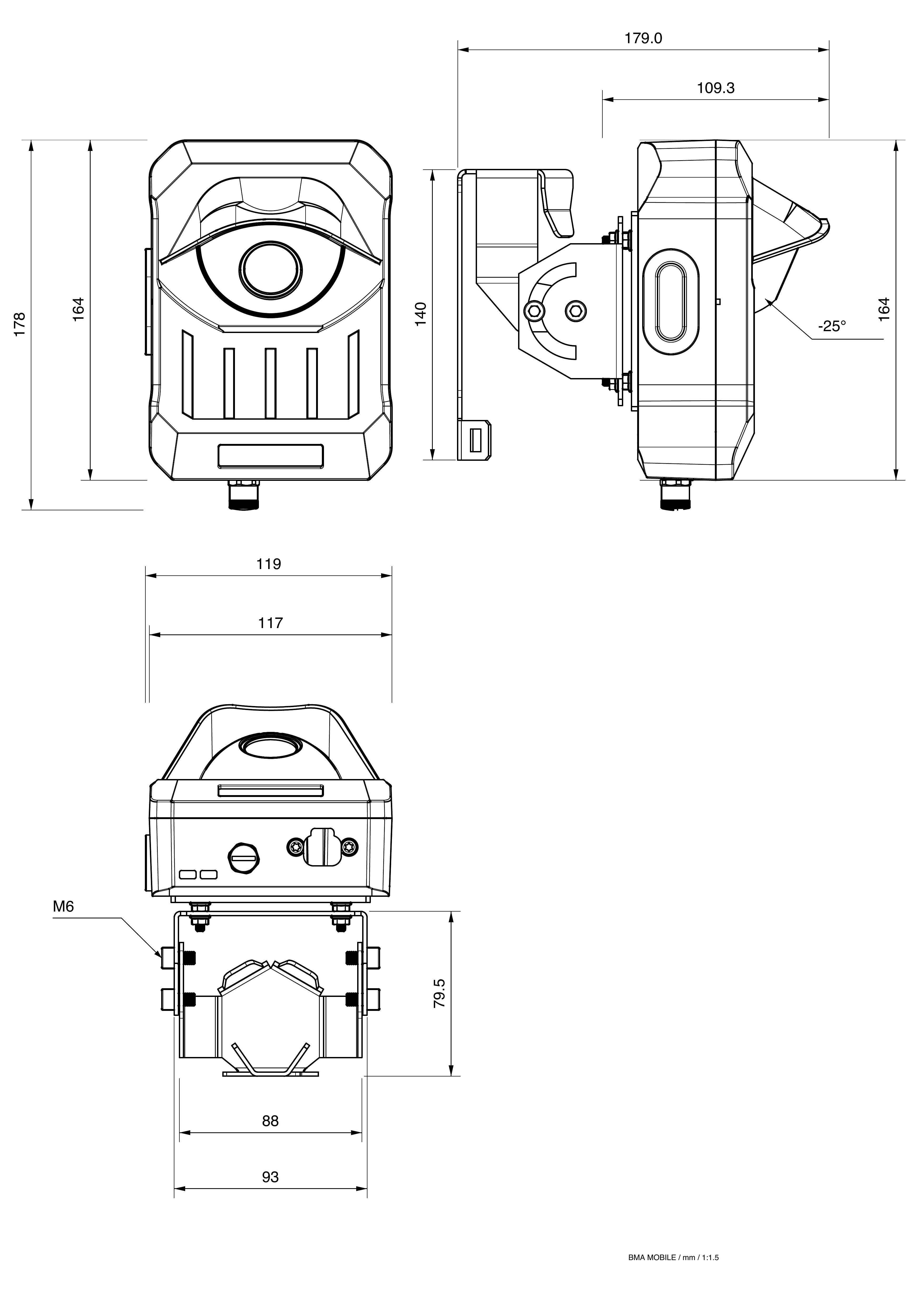
| Device dimensions without bracket | 17.8 cm x 11.9 cm x 10.9 cm (L x W x H) |
| Device weight with bracket | 880 g |
| Battery/mast set (article 100507) | |
| Battery | LiFePO₄, 100 Ah / 1,280 Wh, 12.8 V nominal voltage |
| Permissible battery operating temperature | Discharging: -20 °C to +50 °C Charging: 0 °C to +45 °C |
| Recommended battery storage temperature | -5 °C to +35 °C |
| Battery box | Maximum charging time: 7.5 h Weight: 14.9 kg |
| Telescopic mast/system | Transport length: 1.78 m Maximum system height: 6.05 m Weight of telescopic mast with mounting bracket: 2.1 kg |
Dimension drawing
Distances to objects
The following distance ranges show at which distances objects can be detected depending on focal length and alignment.
BMA Mobile (2.7 mm, hardware revision v3)
| Focal length (mm) | Field of view H/V (°) | Orientation | Person/Bicycle (m) | Car/Van (m) | Truck/Bus (m) |
|---|---|---|---|---|---|
| 2.7 | 93 / 61 | Near range | 0 — 15 | 0 — 15 | 0 — 15* |
| 2.7 | 93 / 61 | Far range | 7 — 20 | 7 — 40 | 7 — 60 |
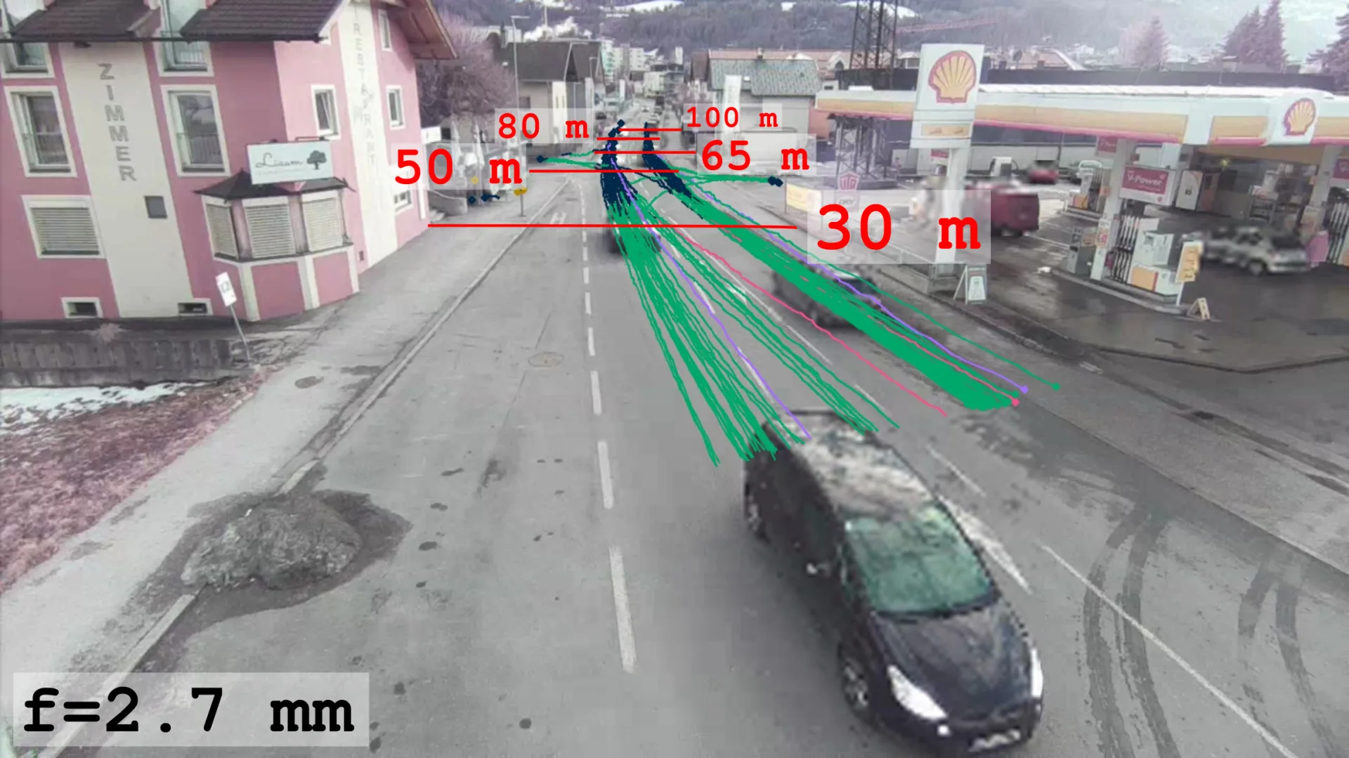
Example view for 2.7 mm focal length (range and field-of-view example).
Legend:
*: Long trucks / buses may not be fully within the field of view.Near range: BMA mounted with a downward tilt.Far range: BMA mounted with an almost horizontal alignment.
Note
Installation height 6 m, clear line of sight, sufficient lighting available.
4. Scope of delivery
Article 100506
☐ 1 x BMA Mobile v3 (2.7 mm)
☐ 1 x hard-shell case
☐ 1 x reusable cable tie
Article 100507
☐ 1 x battery box with 100 Ah / 12 V battery
☐ 1 x 12 V / 15 A charger including charging cable
☐ 1 x carbon telescopic mast
☐ 2 x tensioning straps
☐ 1 x mast lock
☐ 4 x padlocks
5. Mounting and installation
Insert / replace SIM card (optional)
The device is supplied with a SIM card by default. In this case, this section can be skipped.
Electrical safety
Do not replace the SIM card during operation. The device must be de-energized before opening the service flap.
Recommendation
Replace the SIM card before installation in a clean, dry environment at room temperature, not in the field.
Required: tweezers, nano-SIM
-
Open the service flap by carefully pulling out the rubber plug.
-
If present, remove the SIM card. Unlock it by pressing it in and remove it with tweezers.
Note
Make sure the SIM card does not fall into the housing. The housing must not be opened.
-
Insert the new SIM card using tweezers.
-
Close the rubber plug carefully and ensure that it seals completely.
Note
An incorrectly inserted rubber plug can cause leakage and damage the device.
-
If necessary, the APN must be configured in the network configuration of the Service Interface.
Charge the battery box
The following procedure applies to the battery box and charger supplied as article 100507.
Permissible charging temperature
Only charge the battery box at an ambient temperature between 0 °C and +45 °C. Allow a cold battery to warm to at least 0 °C before charging. Only use the supplied charger.
- Ensure that the charger is disconnected from the mains supply.
- Connect the charger to the battery box.
- Connect the charger to the 230 V AC mains supply and select LI-ION mode.
- Monitor the charging status:
- Bulk: charging in progress
- Absorption: charging in progress
- Storage: charging complete
- Disconnect the charger from the mains supply.
- Wait 30 seconds.
- Disconnect the charger from the battery box.
- Verify that the battery voltage is at least 13.5 V DC after charging.
Set up the mobile system
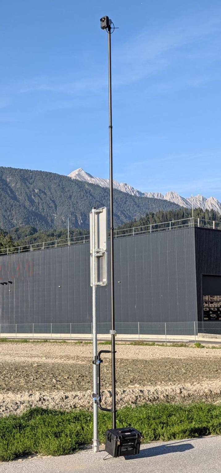
Fully assembled BMA Mobile system.
Site safety
Observe local regulations and obtain any required permit. Do not obstruct roads, footpaths, driveways, traffic signs, or sight lines. Attach the mobile system to suitable fixed infrastructure and secure the work area during setup.
- Position the carbon telescopic mast and mounting bracket against suitable fixed infrastructure, such as a lighting pole or tubular post.
-
Feed both tensioning straps through the two lugs of the mounting bracket, tighten them around the infrastructure, and secure each ratchet mechanism with a padlock.
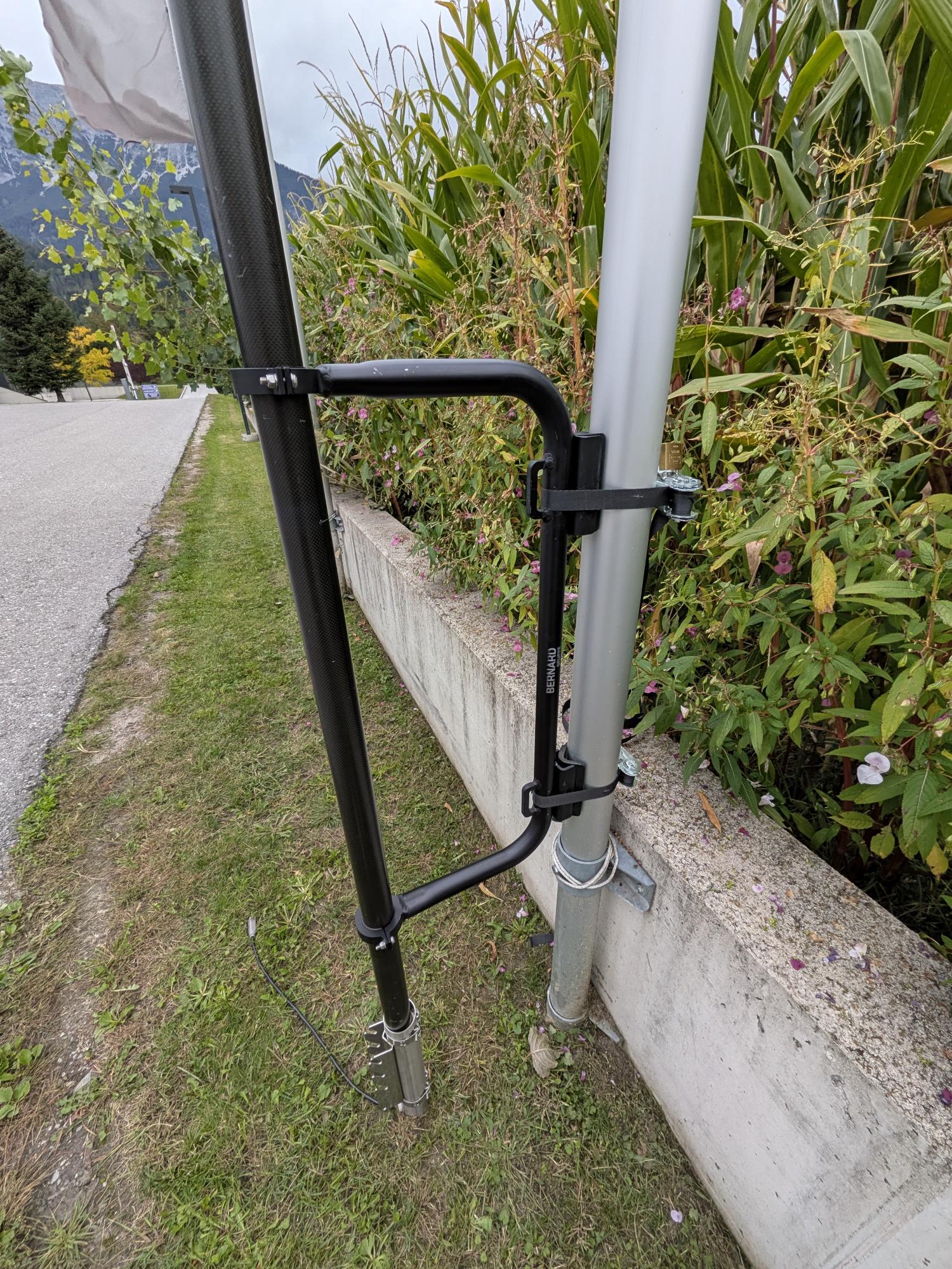
Telescopic mast secured to fixed infrastructure with tensioning straps.
-
Place the BMA detector (article 100506) on the top mast element and lock it in place with a twist-and-push movement. Secure the detector to the lower mast lug using the supplied reusable cable tie, tighten the cable tie by hand, and connect the supplied power cable to the detector.

Detector mounted and secured on the telescopic mast with the power cable connected.
-
Connect the battery-box side of the cable and close the connector lock.

Connection at the battery box (article 100507).
-
Lift the battery box into the center guide of the mast C-profile. Once correctly positioned, secure it with a padlock through the lower hole.

Battery box secured in the mast guide.
-
Release the twist lock of the lowest mast element, extend the element to the required height, and firmly close the lock clockwise. Repeat for the remaining mast elements.
- Check the camera image in the Control Center. Rotate the mast to adjust the horizontal orientation. Fully retract the mast before adjusting the detector tilt.
-
Fit the mast lock around the lowest twist lock and secure it with a padlock.

Lowest mast element secured with the mast lock.
-
Verify that all fasteners are secure, the cable is strain-relieved, and the detector has an unobstructed field of view.
6. Commissioning
- Connect and switch on the charged battery box.
- Expected LED behavior:
- Power LED (left) lights red at first, then flashes red and then turns solid green. Time until the LED remains solid green: < 2 minutes.
- Connectivity LED (right) flashes blue at first and then turns solid green. Time until the LED remains solid green: 3 - 8 minutes.
- If the actual behavior differs, see Troubleshooting.
- Expected LED behavior:
- Setup
- Retrieve the camera image of the device in the Control Center and fine-tune the mounting alignment if necessary.
- Configure the device in the Control Center and configure the traffic survey in the Data Center.
7. Operation / use
7.1 Operation via Control Center
During normal operation, the BMA is managed centrally via the Control Center.
- Perform device configuration: model selection, event triggers, and rule definition. See: Device configuration in the Control Center.
- Monitor device status and connectivity and create alerts: Monitoring & Status, Monitoring Alerts
- Apply updates regularly: Device update
7.2 Service Interface
The Service Interface is intended for local commissioning and on-site diagnostics.
Requirements
- Notebook with Windows 11, macOS, or Linux; Google Chrome is used as the browser (mDNS must be supported).
- Ethernet cable with M12 plug (D-coded, 4-pin) and RJ45 plug.
Access steps
- Connect the M12 plug to the BMA (remove the protective cap from the M12 socket on the BMA first).
- Insert the RJ45 plug into the notebook.
- Under Linux, you may need to select the IPv4 method “Link-Local only” for the network interface.
- Open the browser and call
http://bma.local(direct notebook ↔ BMA connection).- If mDNS is not available for the direct connection, use
http://169.254.42.1as fallback. - If the BMA is integrated into the network via DHCP, access is via
http://<serial-number>.local, e.g.http://G-A2603-0001.local.
- If mDNS is not available for the direct connection, use
- After disconnecting the cable, reattach the protective cap to the M12 socket on the BMA.
Change password (mandatory)
Standard login for the Service Interface: username admin, password = first segment of the device ID (shown in the Control Center up to the first -).
Example: device ID 39b7b668-c7fd-4e91-9d65-b3ab96ebe3f2 → initial password 39b7b668.
The initial password is device-specific and should be changed on first login. Password policy: see Account in the Service Interface.
Note
The Service Interface is intended for on-site service. In normal operation, management is performed via the Control Center.
Functions in the Service Interface
The Service Interface supports service technicians during commissioning, on-site checks, and troubleshooting.
Overview
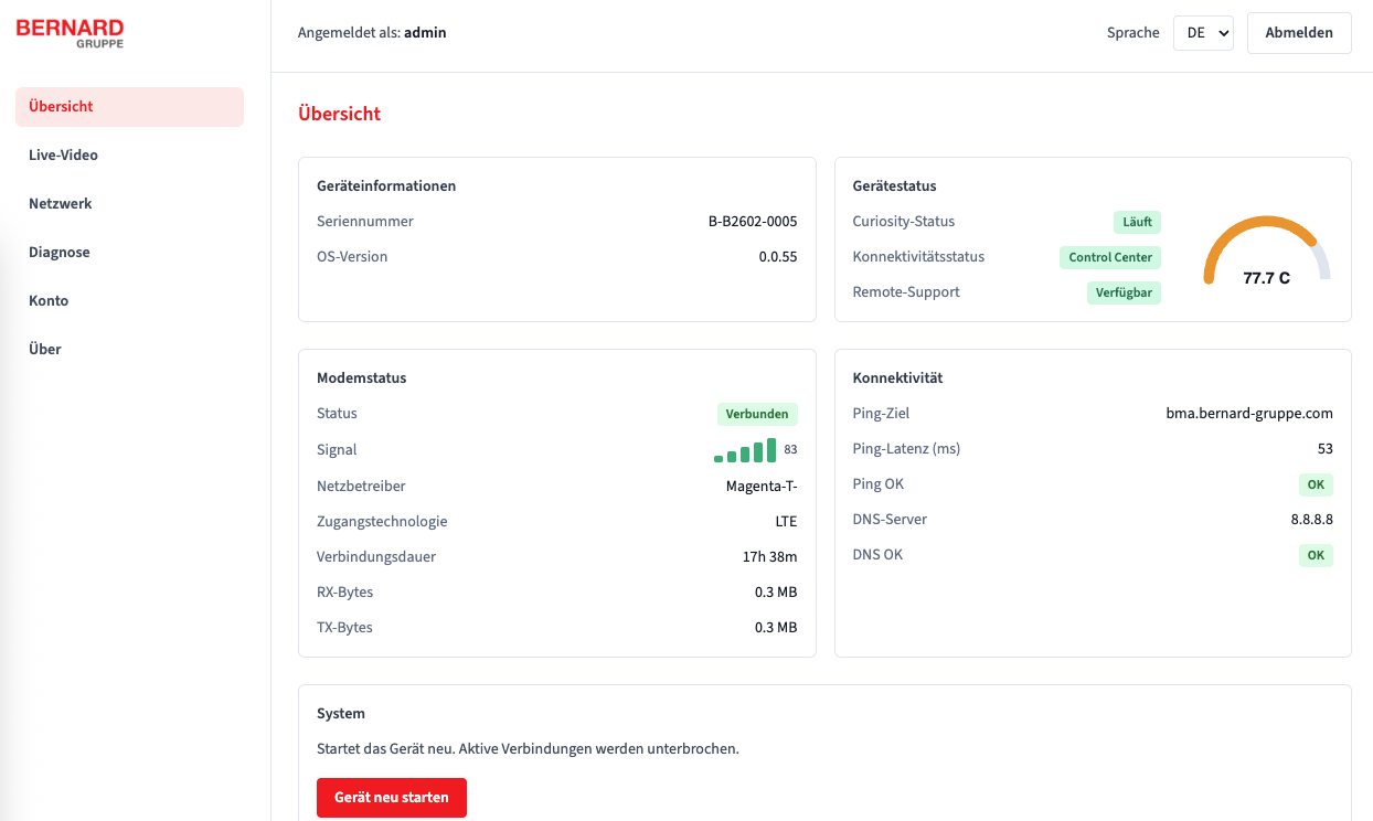
Overview with device, status, and modem information.
- View device information (e.g. serial number, OS version).
- Device status:
- Application status (Curiosity): status of video processing.
- Error: application error (see 8. Troubleshooting).
- Standby: the application is currently inactive.
- Running: application active, processing and rule evaluation operate normally.
- Connectivity status:
- None: no active connection (see 8. Troubleshooting).
- Internet: Internet connection available.
- Control Center: connection to the Control Center active.
- Remote support:
- Available: remote support is possible.
- Not available: remote support is currently not possible.
- Application status (Curiosity): status of video processing.
- Modem status:
- signal strength
- network operator
- access technology
- connection duration
- transferred data (RX = received, TX = transmitted)
- Perform a controlled restart of the device if required.
Live video
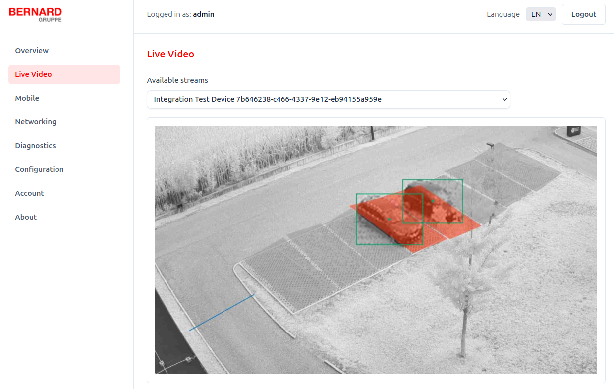
Live video for visibility and alignment checks.
- Select available streams and use the camera image for visual inspection and alignment.
Configuration
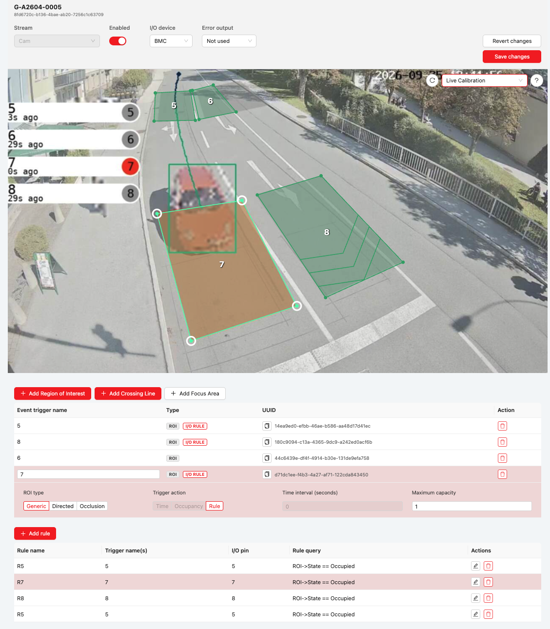
Local configuration of ROIs, Crossing Lines, rules, and the I/O device.
The Configuration page allows you to change the active configuration directly on the BMA. This enables configuration of a device without an internet connection, when configuration via the Control Center is unavailable.
Local configuration is designed for adaptive traffic control and supports regions of interest (ROIs), Crossing Lines (CLs), rules, and, depending on the device, BMC (BMA TLC v3 only) or Quido as the I/O device.
Settings such as the MQTT connection cannot be changed on this page. These settings are only relevant when the device is online and can be configured via the Control Center. An XKOPMV connection is also not supported locally and must be configured in the Control Center.
Mobile
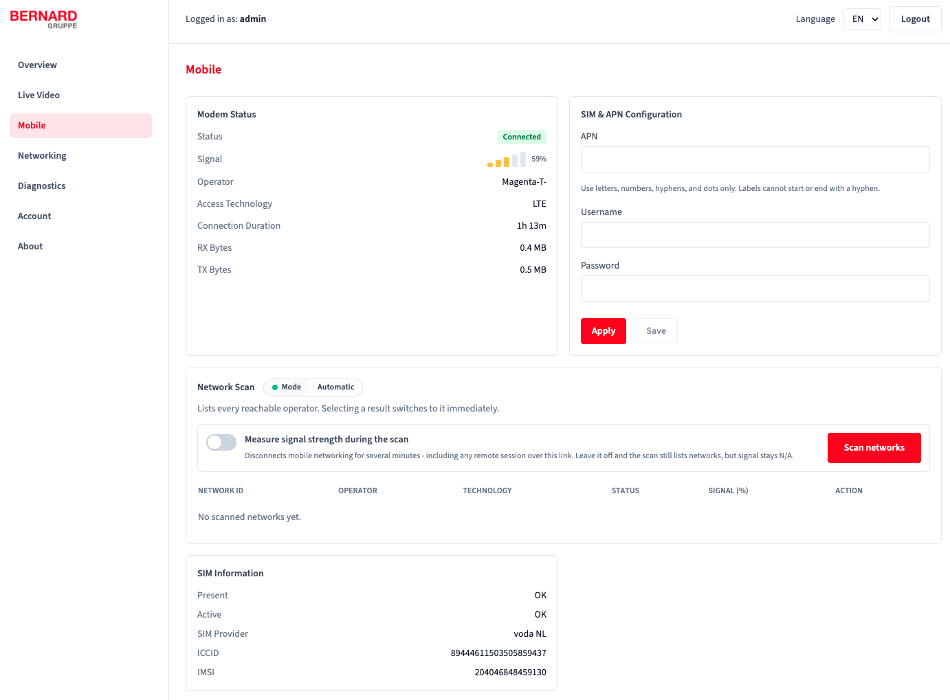
Mobile connection, SIM and APN configuration, network scan, and SIM information.
The Mobile page provides the current mobile connection status, SIM and APN configuration, available-network scanning, and SIM identification details.
- Modem status: Shows whether the modem is connected, the current signal strength, mobile operator, access technology, connection duration, and transferred data volume. The device uses LTE for mobile data connectivity.
- SIM and APN configuration: Configure the APN required by the SIM provider. The username and password are optional and can be left empty when the provider does not require credentials. For SIM cards supplied with the device, these fields should normally remain empty.
-
Network scan: Scans for reachable LTE networks and displays their network ID, operator, availability, and, optionally, signal strength. By default, the device selects the mobile network automatically. After a scan, another available network can be selected manually. A network change is considered successful only after working mobile data connectivity has been verified. GSM networks are not considered during network selection.
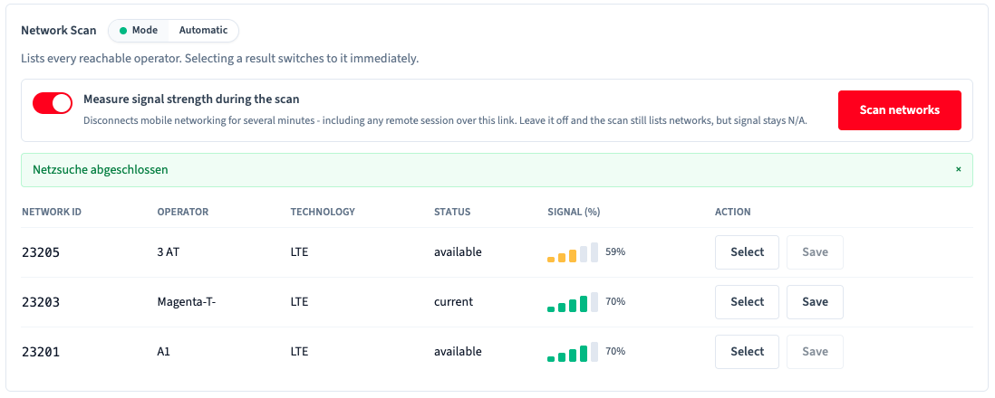
Available LTE networks after a network scan.
Temporary connectivity interruption
Measuring signal strength interrupts mobile connectivity and remote sessions using it for several minutes. Without measurement, networks are listed without signal-strength values.
-
SIM information: Shows whether a SIM card is present and active, together with the SIM provider, ICCID, and IMSI. Use these details to identify the SIM card when diagnosing connectivity issues or contacting support.
Network
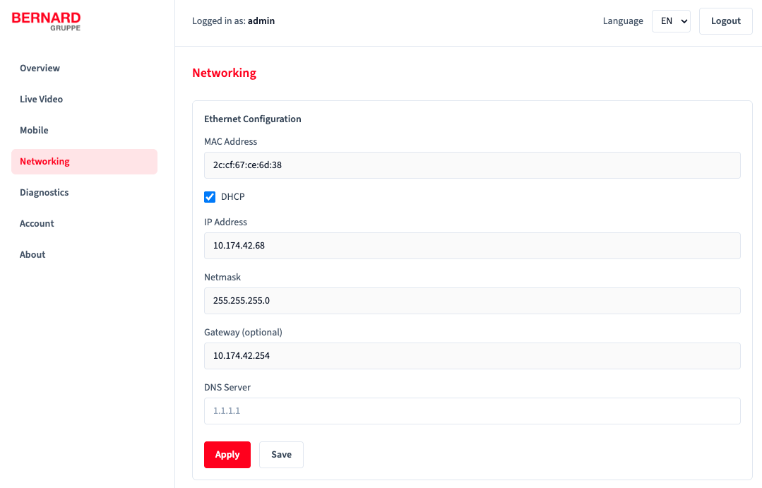
Ethernet configuration in the Service Interface.
The Network page contains the Ethernet configuration of the device. Depending on the network environment, use DHCP or configure the IP address, subnet mask, gateway, and DNS server manually.
Network restrictions
- IPv6 is not supported.
- DHCP addresses must not be within the range
172.17.0.0/16(Docker default network).
Optional gateway
The gateway field can be left empty when internet access is provided through the mobile connection and Ethernet is used only for Event Delivery or XKOPMV without internet access.
Firewall settings: To communicate with the Control Center, the following ports must be open for outgoing connections:
| Port | Protocol | Direction |
|---|---|---|
| 80 | IPv4 - TCP/UDP | Outgoing |
| 123 | IPv4 - UDP | Outgoing |
| 443 | IPv4 - TCP/UDP | Outgoing |
| 1194 | IPv4 - UDP | Outgoing |
| 8883 | IPv4 - TCP | Outgoing |
| 5671 | IPv4 - TCP | Outgoing |
Diagnostics
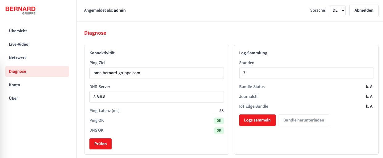
Diagnostics view with ping / DNS test and log collection.
- Perform connectivity tests via ping and DNS.
- Use latency as well as ping / DNS status for troubleshooting.
- Collect logs and provide them for support cases.
Account
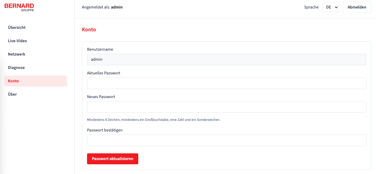
Account management for changing the local service password.
- Change the local service password.
Password policy
At least 8 characters, at least one uppercase letter, one number, and one special character.
8. Troubleshooting
| Symptom | Probable cause | Action |
|---|---|---|
| Power LED does not light up | Battery is switched off, discharged, or not connected correctly | - Check the battery charge state. - Check that the battery and detector power connectors are fully engaged and undamaged. - Check with a multimeter whether 12-48 V DC is present at the detector. |
| Power LED remains permanently red | System not started | Contact support |
| - Power LED flashing red - Application status = Error |
Application error / system application not running correctly | - Collect log files in the Service Interface and provide them when contacting support. |
| - Connectivity LED flashing blue - Service Interface connectivity status = None |
No active data connection (SIM/APN/network) | - Check signal strength in the Service Interface. - Check the APN settings of the network operator in the Service Interface (leave empty for supplied SIM cards). - Check whether the SIM card is inserted correctly. - If necessary, test the SIM card in another device. |
9. Transport and storage
- Retract and secure the telescopic mast before transport.
- Transport the detector, mast, battery box, and accessories secured against movement and protect them from shocks, vibrations, and moisture.
- Protect protective caps / connectors from contamination; avoid tensile load on cables / connectors.
- Transport and store the battery in accordance with the applicable battery safety regulations.
- Store the detector, mast, battery box, and accessories in a dry, low-dust environment.
- Recommended storage temperature for the battery box: -5 °C to +35 °C.
- For prolonged storage, recharge the battery after no more than 3 months.
- Inspect the battery box and connections for damage before storage and before returning the system to service.
10. Maintenance and service
The detector is maintenance-free. Check the telescopic mast, twist locks, mounting bracket, tensioning straps, power cable, and connectors before every deployment. Charge the battery before use and according to the instructions supplied with the charger.
Cleaning:
- Clean the lens / rain hood with a soft, lint-free cloth (slightly moistened if necessary).
- Do not use aggressive cleaning agents, solvents, or abrasive aids.
- Do not use a high-pressure cleaner / no direct water jet on plug connections.
11. Decommissioning and disassembly
DANGER
Switch off the power supply before disassembly and make sure the detector is de-energized.
CAUTION
The metal plate on the rear of the device may become hot during operation.
- Switch off the power supply.
- Disconnect the connector(s) and remove strain relief / cables.
- Retract the telescopic mast completely.
- Remove the detector and disconnect the battery box.
- Release the tensioning straps and remove the mast from the supporting infrastructure.
- Pack all components for transport / storage (see Transport and storage).
12. Conformity and disposal (EU)
Data protection
The detector is intended for the collection of anonymized traffic data. The operator is responsible for compliance with data protection requirements (e.g. GDPR) in the respective deployment context.
Conformity
The product is intended for use in the EU. The device contains a radio module (LTE); therefore requirements of the Radio Equipment Directive (RED, 2014/53/EU), among others, may apply. The EU Declaration of Conformity (DoC) and information on CE marking are available from support.
Disposal
- Collect packaging materials separately and dispose of them in accordance with local regulations.
- Do not dispose of waste electrical equipment in household waste; collect separately and send for environmentally sound recycling.
- Dispose of the battery separately in accordance with local battery regulations.
13. Contact
Manufacturer: Bernard Technologies GmbH, Auweg 20, 6112 Wattens, Austria
If you have questions or problems:
- Support Center: Support
- Email: service@bernard-gruppe.com
- Phone: +43 5223 5840 10160, +49 221 222825 60
- For quick processing, please provide: serial number, hardware revision, installation site, brief description of the fault